spacer spacer spacer
 

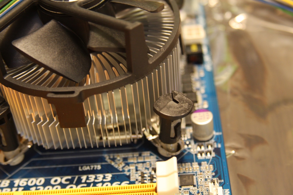
Here I am showing you the way the connectors are supposed to be set up.  You need to check these before trying to install the heat sink or you may never get one to snap in place properly.

The arrow head should not be close to the heat sink.  Turning the arrow head towad the heat sink allows the pin to pop out of the motherboard.


To install the heat sink you get all the clips set onto their holes and then press down on the black piece.  There is a plastic rod that is forced through the white piece and makes the little prongs expand and hold onto the motherboard.


You always want to push the cpu pins in place in an opposite corner fashion. For example, start on the top left, then the bottom right, then the top right and then the bottom left.
I find it easiest to get two pins in and then pick up the motherboard and push the remaining 2 in place with my thumb near the hole where the pin will pop through.

 
spacer spacer spacer
 

This build uses 8 gigs of ram.  Its always wise to buy your ram in dual channel setups, especially when using a motherboard that can make use of the dual channel ram.  This ram that is shown totals 8 gigs but is setup by having two 4 gig sets of two 2 gig sticks, confusing yes?
Basically, this ram was made to work with its brother and needs to be installed accordingly.

 
spacer spacer spacer
 

Here you can see the RAM slots.  There are two yellow and two red.  One pack will go in the yellow and the other pack of ram will go in the red.  This keeps the matched pairs matched.


If you are planning for an upgrade later and are using matched/paired ram now you will want to install the matched stick in either the yellow slots or the red slots, not one in red and one in yellow.

 
spacer spacer spacer
 

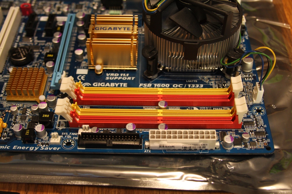
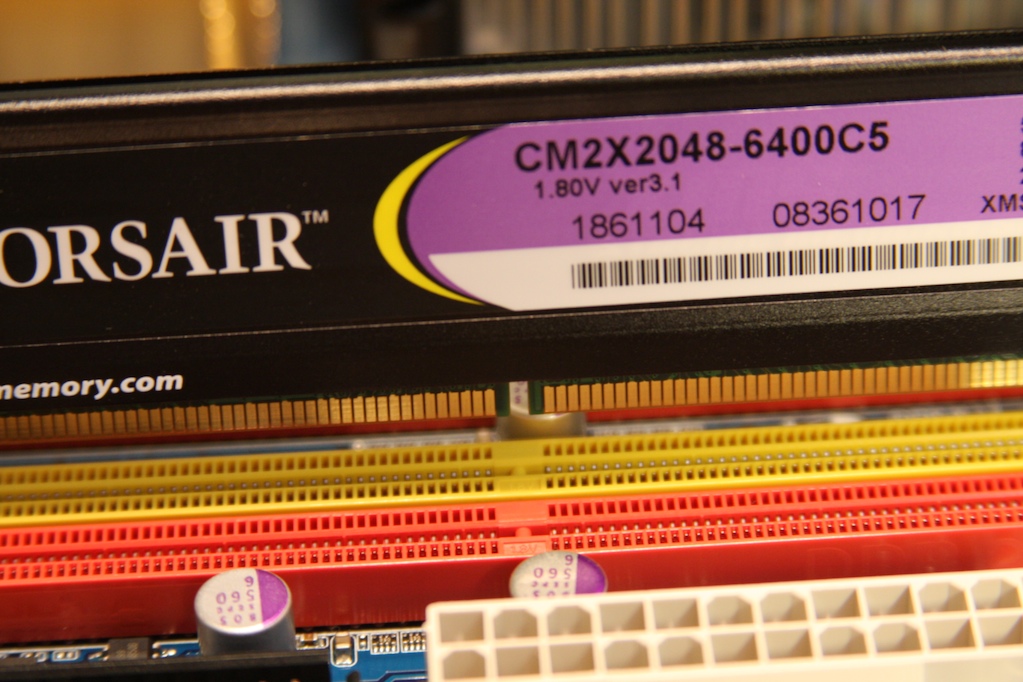
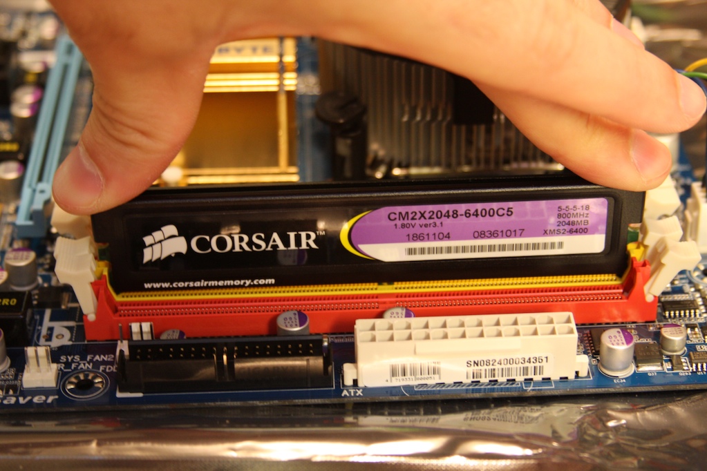
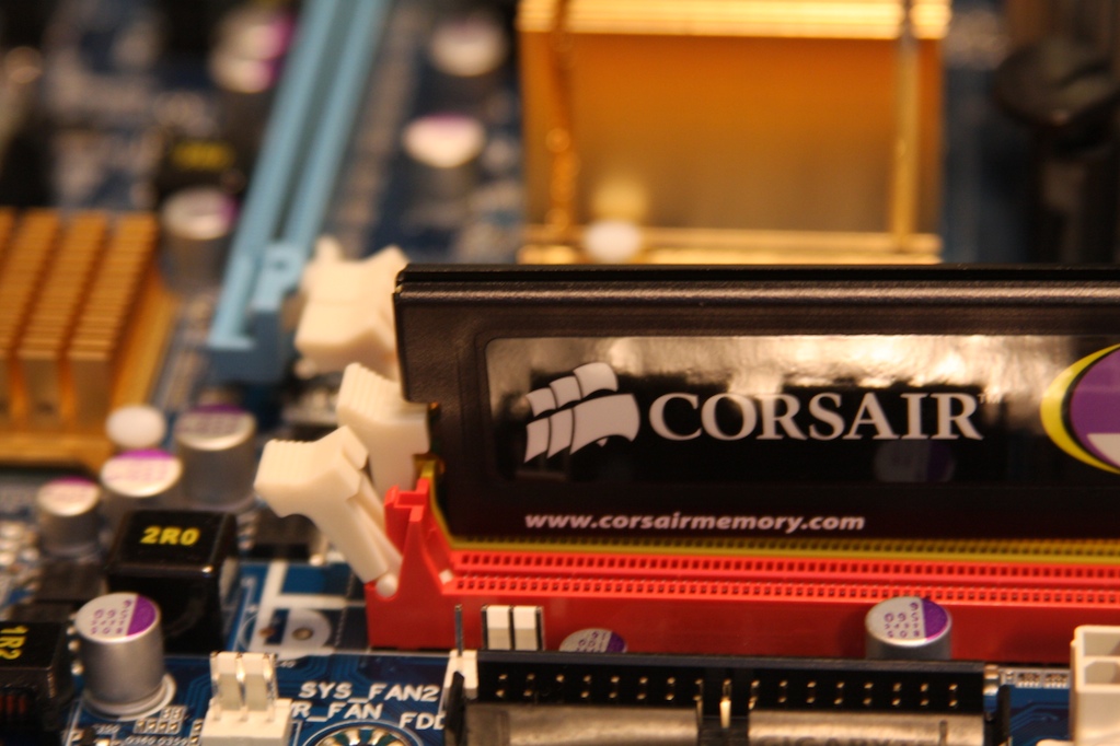
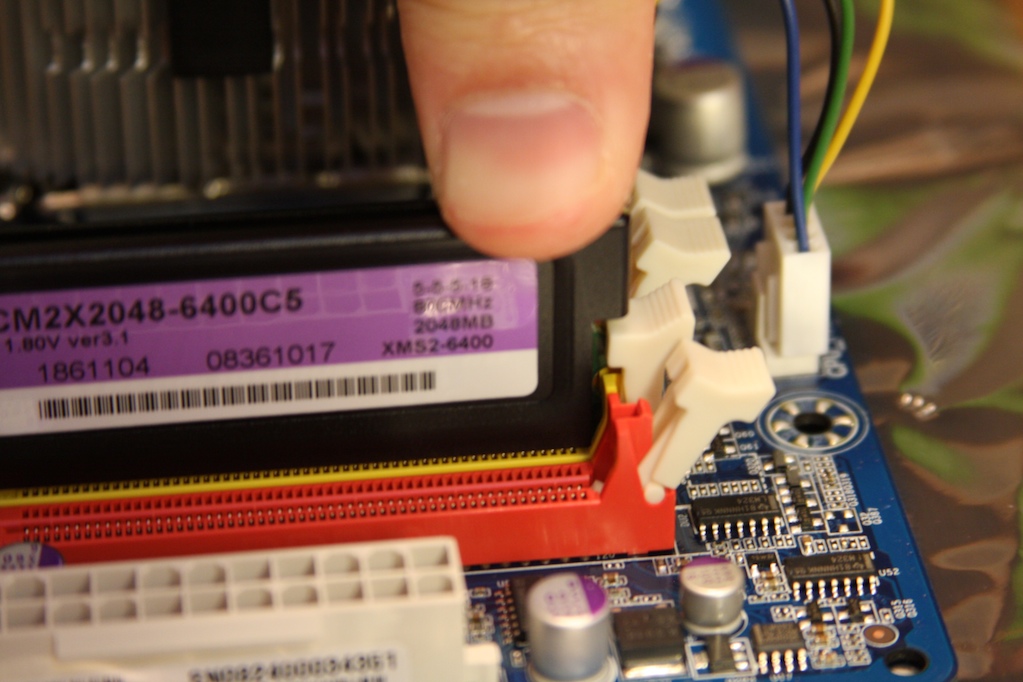
RAM is another component you can’t mess up when installing unless you’re awesome!


One side of the ram is shorter/has fewer teeth than the other and there is a notched that is off-centered.  Match this notch to the notch on the motherboards memory slots and you’re nearly home free.


spacer spacer spacer


When pushing the RAM stick in it is best to apply pressure evenly but still utilizing a slight rocking motion in order to not crack the motherboard. 


spacer spacer spacer
 

Once the RAM is seated correctly the side latches will have closed to tightly to the ram as shown here.
You may need to push on one end a bit more to get it to fully pop in place.

 
spacer spacer spacer
 

Here you can see my matched pair installed correctly.  This is one pack of ram installed in a matched setup.

 
spacer spacer spacer


Once the CPU and RAM are installed the next step is to finish prepping the case to receive the motherboard.


The input panel is in place now you have to install the risers that shipped with the case.

 
spacer spacer spacer
 

The risers look like this, the bottom half screws into the case allowing a gap between the motherboard and the case.  This gap keeps the motherboard from short circuiting and frying all your beautiful equipment.


spacer spacer spacer
 

This case is punched to accept three different types of motherboards; ATX, micro ATX and extended ATX.  You will be using 6 of these holes for a standard ATX motherboard (although my cheap case only came with 5 risers.)


spacer spacer spacer
 

It’s usually easiest to grab the motherboard by the CPU heat sink and hold it over the holes to find out which ones line up.  This technique will also test how well or poorly you installed your fan heat sink!


spacer spacer spacer
 

Make sure your risers are installed all the way in, failure to install them all the way may result in an annoying humming noise that you may not be able to pinpoint later.


spacer spacer spacer
 

On the motherboard you will see the holes for the screws that hold the motherboard to the risers are sporting a bit of seemingly random solder.  Most of the time this solder actually is used to “connect” the motherboard to the case, to ensure proper grounding.  Sometimes its just so the screw has something to sink into.


spacer spacer spacer
 

This case came with 3 different style screws.  For the motherboard ill be using the middle one, it has a finer thread than the others, its also the only one that screws into the risers!


spacer spacer spacer
 

So now the motherboard is locked in, while I have the case on its side I will just go ahead and slide the optical drive into its bay.  This case refused to let me slide the optical drive through the front opening so I had to slide it through the back.


spacer spacer spacer
 

Place a screw in the correct holes.  I used the same screws for this as I did on the motherboard.


spacer spacer spacer
 

Although I forgot to take a picture of it, the opposite side panel is removed in the same fashion as the windowed side.  Just two screws hold it in place then you pull backward and lift it away from the case.


spacer spacer spacer
 

With the optical drive in I can now install the power supply.  This power supply is almost modular.  Unfortunately it has wires protruding out of the case about 4 inches and the other wires are supposed to plug into those protruding wires.


spacer spacer spacer


spacer spacer spacer
 

Here I used the larger screws that came with the case since my power supply didn’t come with any screws, for whatever reason.  4 screws are used to install the power supply, I’m half way there.


spacer spacer spacer
 

At this point I usually check to make sure my voltage switch (red) is set correctly.  In the US its 115… check.


spacer spacer spacer
 

Im going to go ahead and forgo my own advice and install the hard drive now, just for the sake of explanation ease.  If I install it after the video card it will be harder to identify everything in the pictures with all the wires.


spacer spacer spacer


spacer spacer spacer
 

This is the end of the hard drive that needs to face into the case, toward the motherboard.  On the left is the power connector, the next one in is the SATA plug receptacle, and the end with the two prongs is a jumper setting.  The jumper setting specifics are usually marked on the hard drive label, most hard drives are set up so that if there is no jumper it performs at 3.0 Gb/s.  Should you need to limit the speed of the hard drive you can use a jumper.


spacer spacer spacer
 

I usually try and fit the hard drive in front of the fan, either on the top half or bottom half, avoiding the dead center as this usually just spreads the air as soon as it hits the front of the drive; making it nearly ineffective.


spacer spacer spacer
 

I will go ahead and lock in the hard drive by installing all four screws, I just test and see which screw fits the hard drive and use those.  The screws I used for the power supply fit this drive.  Some drives use a finer thread screw and any retail packaged drive usually ships with a pack of screws.  I haven’t ever had the case’s packaged set of screws not work on my hard drive and optical drive.


Some cases give you isolators, or little pads, to put between the case and the drive and/or the case and the screw to keep any vibration to translating to noise and quickly becoming annoying.  They’re not necessary but are convenient.


spacer spacer spacer
 

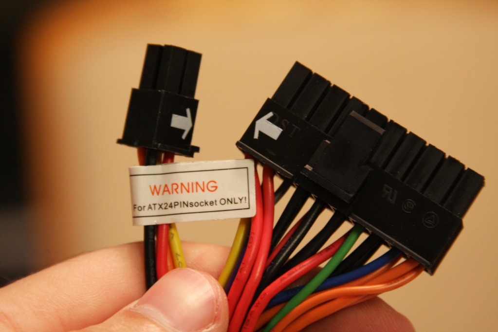
Back to hooking up the power supply wires.


The first connection I always make is the one wire that isn’t “modular” ever, that’s the motherboard power connection.  This motherboard uses a 24 pin connection. 


The power supply is set up for a 20+4 pin so it can be used for a 20 pin or 24 pin motherboard.


spacer spacer spacer


spacer spacer spacer
 

The power supply is set up for a 20+4 pin so it can be used for a 20 pin or 24 pin motherboard.


spacer spacer spacer


spacer spacer spacer
 

Since there are so many steps to this tutorial i have broken it down into 3 seperate pages.

Continue on....


                                  Page 1                      Page 2                      Page 3


spacer spacer spacer